상품상세 정보


Event

![]() 2007-2008 The BEST BUY components No.2
2007-2008 The BEST BUY components No.2
 Audio Excellence Award 2008, Bronze
![]() The 26nd MJ Technology of the year
The 26nd MJ Technology of the year
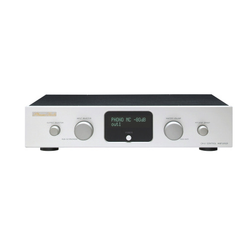
Analog disc playing has deeply improved on the present popular digital audio sources, and now along combined is an individual phono amp seeking more of a sound quality.Therefore the functions sought in the previous phono amp is consolidated to the signal source selection and volume adjustment. It is becoming to be the control center of the system.This time we made good use of the semi-conductor circuit technology, maintained Phase Tech’s developmental thoughts, and developed a 3series control amp CA-3 which expanded the ideal volume adjustment circuit which is the core technology introduced in CA-1.

Volume Adjustment Circuit Actualized With an Ideal Gain Control
The “hybrid gain control circuit” is introduced that was developed in the upper class model CA-1. For this circuit, an ideal gain control is made possible in order to prevent signal power losses sent from the source device due to the impedance matching theorem.As a result, the main unit’s volume adjustment circuit has enough volume resolution (46 levels) to actualize an absolute non-use of active elements, high input impedance and low output impedance. Even if the volume is dropped, the osmotic force is maintained and can be enjoyed having no sound diminishing.This unit uses an electric switch for gain switching but in order to prevent sound quality diminishing due to a cascade connection of the electronic switch, it is made up of a 48-step 1-phase attenuator although the scale becomes large.The electronic switch which is the gist is introduced with a factory analog multiplexer IC 10 times more of a high resistance pressure than the previous ones and guarantees enough dynamic range and linearity.

Amplifier Circuit Due to the Semiconductor Element
Our original FULL SYMMETRICAL NON-FEEDBACK CIRCUIT: TM evaluated in EA-3 is introduced into the amp for all steps.To aim for an enlargement of music expression, all steps are symmetrical non-feedback circuits due to electric current amplifying operations fit for the semiconductor. As a result, music play with full of excitement and a rich expression and plus a “gradational expression of rich sound, excitement and S/N feeling, and excelled open-air expression compatibility is accomplished which is possible only with a non-feedback circuit.
The first grade ones due to complementary FET (electric field effect transistor) connections, an extremely low noise voltage current conversion circuit is structured.Since operation points are decided due to self biased operations for strictly selected elements, biased circuits are unnecessary and there are no noises flowing in or sound quality deteriorations but the element’s original low noise operation of elements.
The first grade units carefully maintain the excellence in fast response having high sound quality and low GmGET and used selectively.
The second step structures an electric current amplification and a voltage conversion circuit and has a stable gain characteristic which is voltage-converted due to a high stable fixed resistor connected to the electric current output point and has stable transient characteristics even for very high frequency areas.For this circuit, various circuit techniques are included having high accurate performances without receiving any electric current conversion tolerances or parametric changes of amplified elements that are dependant on the output voltage. Although it is a non-feedback type amplifier, it has various excelled characteristics that makes it to be equal as a feedback type amplifier.
The output buffer circuit guarantees a high input impedance crossing over a wide area due to an input boost wrap and the output element with a Darlington connection holds enough electric amplification and at the same time drives the next connected device strongly.
The balance output reverse signal generation circuit is a non-feedback structure due to a 1-step conductance amp and unlike the reverse amps of the previous OP amps, it accomplishes an accurate reverse operation of a wide area without any punch-through phenomena. (note 2)
(note 2: a phenomenon where an input signal in phase with the same positive phase signal is outputted instantly when a fast signal without forming a negative feedback operation is inputted.)
A Simple Signal Transmission
The control amp was narrowed down to the necessary functions without passing through any redundant points but maintained the purity of the signals. Correspondences can be made if the DSP, etc. exterior sound quality adjustment device utilizes the EXT. PRO input/output circuit of this unit.The balance adjustment is done by offsetting the attenuation level of the LR of the “hybrid gain control circuit,” and omits redundant gain adjustment structures which is the cause of deterioration of the sound quality.”For a control amp with multiple source signals together, in order to maintain the signal purity, the input circuit design is important but by arranging the mechanical relay of the enclosed gas type for this unit, it will not accept the disturbances from others but accomplishes a simple signal transmission having no resonance, no vibration, and no interferences.
Dual monaural construction
From the power circuit, this equipment composes the symmetrical dual monaural construction completely and actualizes the advanced uniformity of the right and left channels. (The L and R are in common for the power transformer)This equipment supplies an ideal power without parameter changes from power loads due to the left/right independent power transformer and the shunt type local power supply. The channel separation with 90dB or more (20Hz-20KHz) has been achieved by minimizing the loop of the circuit current.

Direct grounding construction of the power transformer
For this unit, in order to prevent sound quality deterioration due to the mutual interference via the analog circuit and control digital circuit power supplies, a specified transformer is used for each.These R-core type power supply transformers of this unit with a large core operates with extra space due to the magnetic flux density and reduces magnetic vibration and leakage of flux as much as possible.In addition, this transformer is assembled directly to the foot of carved high carbon-steel stick through the 5mm thick bakelite board that is an insulator with high electric/magnetic resistance. As a result, the vibration from which the power transformer generates is discharged into the earth at once without transmitting to the chassis.

[Specifications]
Model Control amplifier loaded with an impedance matching volume adjustment circuit
Input Sensitivity 200mV
Input Impedance 47KΩ
Gain 17dB(unbalance)
23dB(balance)
Residual Noise -103dBV(7μV):A-NET
Channel Separation 90dB以上(20~20kHz)
Rated Output Voltage 1.5V(1KHz)
Frequency Response 5Hz~80kHz(+0,3dB)
Output Impedance 150Ω(unbalance,balance)
Balance output pin setting 1pin=GND
2pin=HOT(+)
3pin=COLD(-)
Power Consumption 12W(100 )
[Phase-Tech 소개]
Phase Tech은 Kyodo Denshi Engineering 주식회사에 속한 오디오 브랜드입니다.
KDE는 설립 이래로 회로, 정밀 메커니즘과 알고리즘에서 3대 핵심 기술을 바탕으로 IT 산업에서 신뢰성 있는 측정 장비를 공급해 오고 있습니다.
동사는 이 하이 테크놀리지를 오디오 분야에 적용해 기존에 장비들에서는 실현될 수 없던 음악 재생과 기술 성과를 이룩했습니다.
[Phase-Tech 정책]
사용자가 제품을 가능한 오랫동안 사용할 수 있도록 한다.
오랜 시간이 지나도 개선시킬 필요가 없을 정도로 완벽한 제품을 만든다.
완벽한 소비자 지원 및 제품 AS
REVIEW
게시물이 없습니다
Q&A
게시물이 없습니다
PAYMENT INFO
무통장 입금은 상품 구매 대금은 PC뱅킹, 인터넷뱅킹, 텔레뱅킹 혹은 가까운 은행에서 직접 입금하시면 됩니다.
주문시 입력한 입금자명과 실제입금자의 성명이 반드시 일치하여야 하며, 7일 이내로 입금을 하셔야 하며 입금되지 않은 주문은 자동취소 됩니다.
DELIVERY INFO
- 배송 방법 : 택배
- 배송 지역 : 전국지역
- 배송 비용 : 무료
- 배송 기간 : 3일 ~ 7일
- 배송 안내 : - 산간벽지나 도서지방은 별도의 추가금액을 지불하셔야 하는 경우가 있습니다.
고객님께서 주문하신 상품은 입금 확인후 배송해 드립니다. 다만, 상품종류에 따라서 상품의 배송이 다소 지연될 수 있습니다.
EXCHANGE INFO
- 상품을 공급 받으신 날로부터 7일이내 단, 가전제품의
경우 포장을 개봉하였거나 포장이 훼손되어 상품가치가 상실된 경우에는 교환/반품이 불가능합니다.
- 공급받으신 상품 및 용역의 내용이 표시.광고 내용과
다르거나 다르게 이행된 경우에는 공급받은 날로부터 3월이내, 그사실을 알게 된 날로부터 30일이내
교환 및 반품이 불가능한 경우
- 고객님의 책임 있는 사유로 상품등이 멸실 또는 훼손된 경우. 단, 상품의 내용을 확인하기 위하여
포장 등을 훼손한 경우는 제외
- 포장을 개봉하였거나 포장이 훼손되어 상품가치가 상실된 경우
(예 : 가전제품, 식품, 음반 등, 단 액정화면이 부착된 노트북, LCD모니터, 디지털 카메라 등의 불량화소에
따른 반품/교환은 제조사 기준에 따릅니다.)
- 고객님의 사용 또는 일부 소비에 의하여 상품의 가치가 현저히 감소한 경우 단, 화장품등의 경우 시용제품을
제공한 경우에 한 합니다.
- 시간의 경과에 의하여 재판매가 곤란할 정도로 상품등의 가치가 현저히 감소한 경우
- 복제가 가능한 상품등의 포장을 훼손한 경우
(자세한 내용은 고객만족센터 1:1 E-MAIL상담을 이용해 주시기 바랍니다.)
※ 고객님의 마음이 바뀌어 교환, 반품을 하실 경우 상품반송 비용은 고객님께서 부담하셔야 합니다.
(색상 교환, 사이즈 교환 등 포함)
